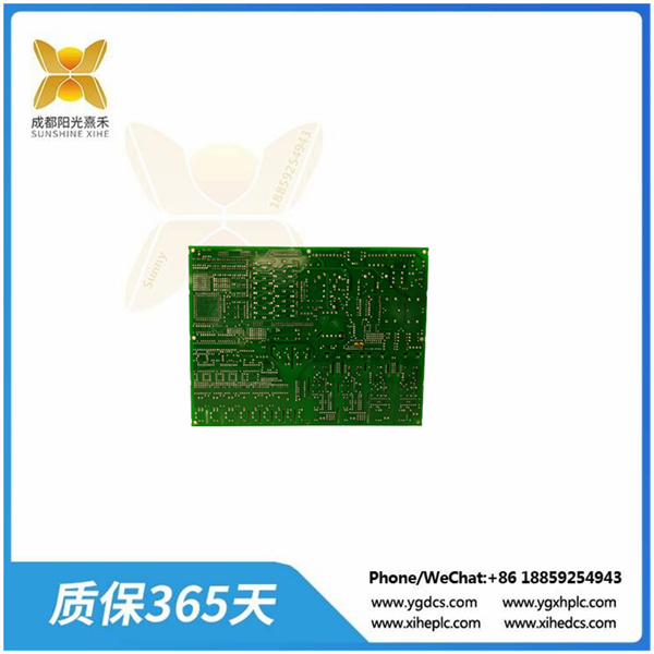
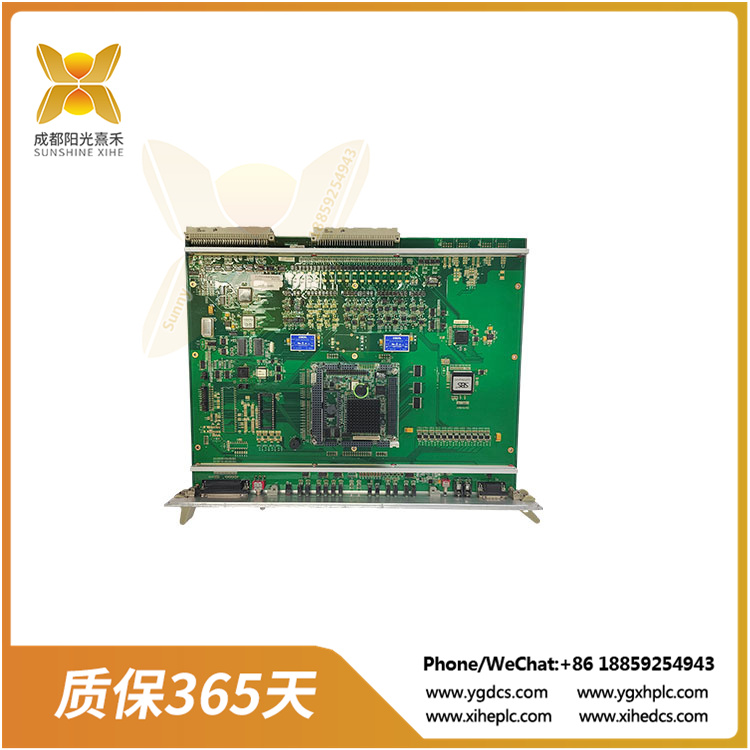
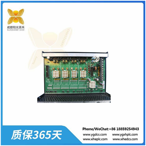
DS200VPBLG1A General Electric Controller Card Control Module Digital
What is the tachometer setting for this board?
There are two tachometer settings on the DS200VPBLG1A board, one is a twelve pin wiring terminal, and the other is a jumper used to configure tachometer settings. There are 10 naming conventions and separate descriptions for terminal connectors, some of which are E0V2, which is the speed measurement power supply V1- (common node choke), and E1V1 is the speed measurement power supply V1+(common mode choke).
Email:18005021035@163.com
Phone:+86 18005021035
Name:BeiLin
Content details
DS200VPBLG1A General Electric Controller Card Control
Module Digital and analog power supply
★★★Product detail★★★

Product Name: GE
Model: DS200VPBLG1A
Warranty service: 365 days
Available for sale: Nationwide
Shipping method: Express delivery
Weight and size: KG/inch
Packaging: Original packaging
Origin: Origin
Customs HS code: 85371011.90
Delivery time/ordering cycle: 3-5 days/3-4 weeks
Payment method: 30% advance payment
Delivery method: Final payment settlement and shipment
Common questions about DS200VPBLG1A
What is DS200VPBLG1A?
DS200VPBLG1A is a GE VME backplane used for load commutator inverter control systems and a 13 slot chassis.
What is the purpose of the J2 and J3 parts on the DS200VPBLG1A model?
The J2 section on the DS200VPBLG1A board is used to support multiple boards, including the DSPC board, up to three door allocation and status boards, one I/O expander, and one exciter board with two spare slots. The J3 section is usually used for external connections that are not located on the front of the circuit board due to space or other limitations.

What is the tachometer setting for this board?
There are two tachometer settings on the DS200VPBLG1A board, one is a twelve pin wiring terminal, and the other is a jumper used to configure tachometer settings. There are 10 naming conventions and separate descriptions for terminal connectors, some of which are E0V2, which is the speed measurement power supply V1- (common node choke), and E1V1 is the speed measurement power supply V1+(common mode choke).
What is the best method to remove the VPBL board for replacement?
First, turn off the power to avoid electric shock. If the connected ribbon cable does not have a pull tab, gently grasp the cable connector and pull it loose. If the ribbon cable has a pull tab, be careful when pulling. Remove all screws, then keep the circuit board level and carefully remove the VPBL.
How many test points are there on the DS200VPBLG1A board?

C0136-HZ
There are 60 spring ring test points used to access the three-phase AC power on the input power supply and the digital and analog signals generated by positive and negative DC outputs. Test points 55 and 62 to 118 are assigned to the pins in the J2 connector for factory use only.
Product Description
The General Electric VME backplane DS200VPBLG1A is a multi-layer board that can separate the digital and analog power layers. The model also has bypass capacitors and distribution at each power connection point in each slot. Within the circuit board, there are two different parts, namely J2 and J3. The J3 section of a circuit board is typically used for all external connections that are not available on the front of the circuit board. The J3 section will also establish a power connection with the backplane.
The DS200VPBLG1A board has a diagnostic connector. This diagnostic connector is a 26 pin discrete cable connector. The main function of the diagnostic connector is to provide input/output connections for the J1 processor. The model also comes with several different tachometer settings, with the two main settings being jumpers and wiring terminals. Jumpers are crucial in this model as all tachometer signals are transmitted through these jumpers.
There are a total of 60 test points on the DS200VPBLG1A model. These test points are spring rings that can access digital and analog signals triggered by three-phase actuator currents from two input power sources, as well as positive and negative DC outputs.


